
Recently, I have been using a lot of AVR chips and I faced few problems regarding burning the code on these chips using commercial AVR programmers. So, I decided why not building my own AVR programmer and get rid of all of this hassle. And, why not customize it according to my needs.
Tiny AVR Programmer Background
Today, we will take a look at how this board is designed, and I will take you on a journey on how each component is working in this design.
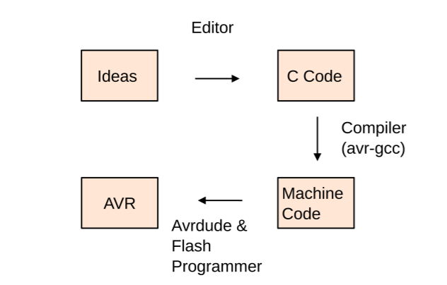
If you have just an AVR chip, you need something to program it. the most common way is through ICSP(In-circuit serial programmer). simply, it’s a board that has 6 pins usually a 0.1″ pitch header that can talk to your AVR chip through the SPI protocol. At the other end, it also can talk with your PC through the USB protocol. So, after compiling your C code using avr-gcc, the programmer board will take and send it to your AVR chip directly. You can think of it as a bridge between your PC and your AVR chip.
I did my research for AVR programmers and I found a lot of cool resources. this one specifically caught my eye. It’s the FabOptimus AVR programmer built by Ali Shtarbanov which built on the FabISP programmer built by prof. Neil from MIT Media Lab. the FabOptimus documentation is very good and easy to follow if you are a newbie. I decided to make a very small modification to the FabOptimus AVR programmer since it doesn’t have a power indicator LED, I wanna add one!


PCB Design And Circuit In-depth Analysis
First, we need to understand how this board is designed and how each component in this circuit is behaving.

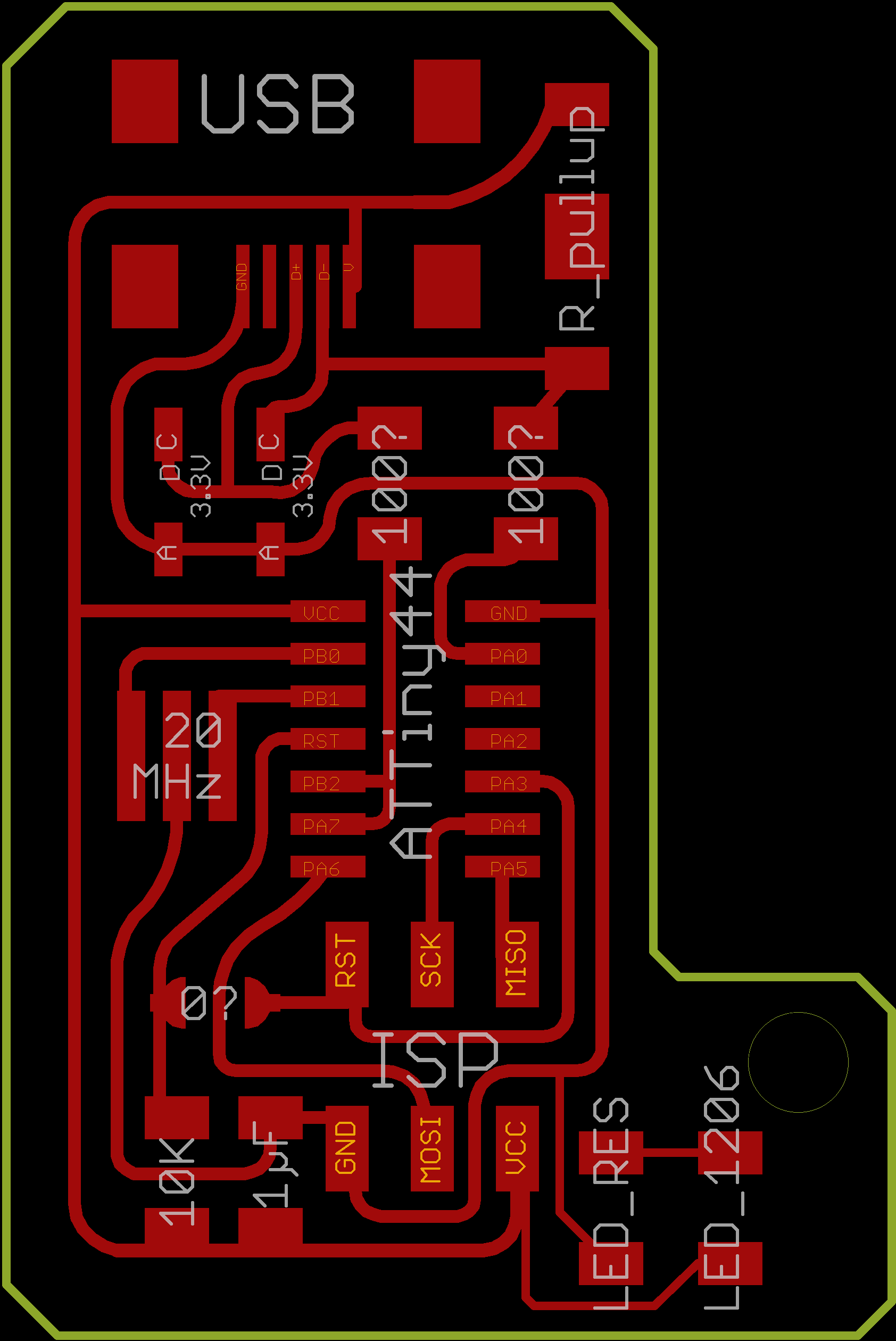
This AVR programmer is based on the ATtiny44 AVR chip which by default it comes blank, no code or anything is uploaded to it like any microcontroller chip you buy. Since we are building an AVR programmer, we need to upload a very specific firmware to the ATtiny44 chip that tells exactly the role it should follow and execute. Simply, which is sending some hex files to other AVR microcontrollers. This firmware is called FabISP firmware(more on that later.)
So, we need to be able to upload the FabISP firmware to the programmer AVR chip then disable the possibility of reprogramming it.

To be able to upload the FabISP firmware to the programmer AVR chip we need to pull its reset pin to LOW(0 volts). and to disable the possibility of reprogramming it once it has been programmed, we need to pull its reset pin to be always HIGH(5 volts). So, we need to design the circuit in such a way that the reset pin is HIGH(5 volts) by default. But, once another programmer is connected to it, it can pull the programmer AVR chip reset pin to LOW(0 volts). That’s why we are using a 10k ohm pull-up resistor on the reset pin.
As you notice the ATtiny44 chip reset pin is connected to the RST pin on the ISP pin header through a 0 ohm resistor. after uploading the firmware to the ATtiny44 chip we will remove this zero ohm resistor to disable the possibility of reprogramming the board again.

Since we need to use our programmer board to program other AVR boards, our programmer board will need to be able to provide the reset signal to the other AVR boards that we need to program. So, we are also connecting an I/O pin from the ATtiny44 chip to the RST pin of the ISP pin header to provide the reset signal to the other AVR chips that we need to program.

To reduce any high frequency noise or any voltage drops coming from the power supply we are using 1uf decoupling capacitor between the VCC(5 volts) and GND.

We also using a 20MHz resonator as a clock source for the ATTiny44 chip instead of it’s internal clock to achieve more accuracy.

We are using two 3.3v Zener diodes as voltage clippers to regulate the voltage from 5v to 3.3v. According to the V-USB and USB specifications, the voltage on the USB data lines should not exceed 3.3v. Also, we are using a 1.5k ohm pull-up resistor on the D- pin of the USB to make it recognizable as a low-speed device on the host side.

Finally, I made a simple edit to the board. I added a power indicator LED to the board.
It’s a best practice to disconnect the VCC pin on the ISP pin header to make sure that the AVR programmer is not attempting to supply power to the board that we want to program. the board that we want to program should provide its own power. If we didn’t disconnect the VCC pin on the ISP header, the AVR programmer and the board being programmed will draw their current from the USB port(from your computer). if your USB port can’t supply that much current or at any short circuit circumstances, that may cause a huge problem to your computer.
PCB Manufacturing

As you can see, I fabricated this board using a CNC milling machine at Fab Lab Egypt. But, if you are searching for high-quality PCB manufacturing with a solder mask and silkscreen at a very fair price and fast worldwide shipping with no minimum requirements you may order as small as 10 pieces for 5$. you can order yours from PCBWay. You can also support me by just ordering this board from my link.
We love open source. You can download all the board source files from my Github repo.
PCB Soldering And Components Placings

| Part Name | Quantity |
| ATTINY44A microcontroller chip | 1 |
| CER RESONATOR 20.00MHZ SMD | 1 |
| MINI USB2.0 5POS | 1 |
| 6 Positions Header Connector 0.100″ SMD | 1 |
| CAP CER 1UF 50V 10% SMD 1206 | 1 |
| RES 10.0K OHM 1-4W 1% 1206 SMD | 1 |
| RES 1.0K OHM 1-4W 1% 1206 SMD | 1 |
| RES 499 OHM 1-4W 1% 1206 SMD | 2 |
| RES 100 OHM 1-4W 1% 1206 SMD | 2 |
| DIODE ZENER 500MW 3.3V SOD123- | 2 |
| LED Blue CLEAR 1206 SMD- | 1 |
Uploading The Firmware To The Programmer
To upload the FabISP firmware to the FabISP AVR programmer board, we need another programmer to help us upload the firmware to our FabISP board. we will use an Arduino UNO board as an ISP programmer and we will connect it to our FabISP AVR programmer board.
First, we need to upload the “ArduinoISP” sketch to the Arduino UNO board. You can find that sketch from files->Examples->ArduinoISP->ArduinoISP.

After uploading it to the Arduino UNO board. Let’s connect our FabISP AVR programmer(Target) with the Arduino UNO board(Programmer).
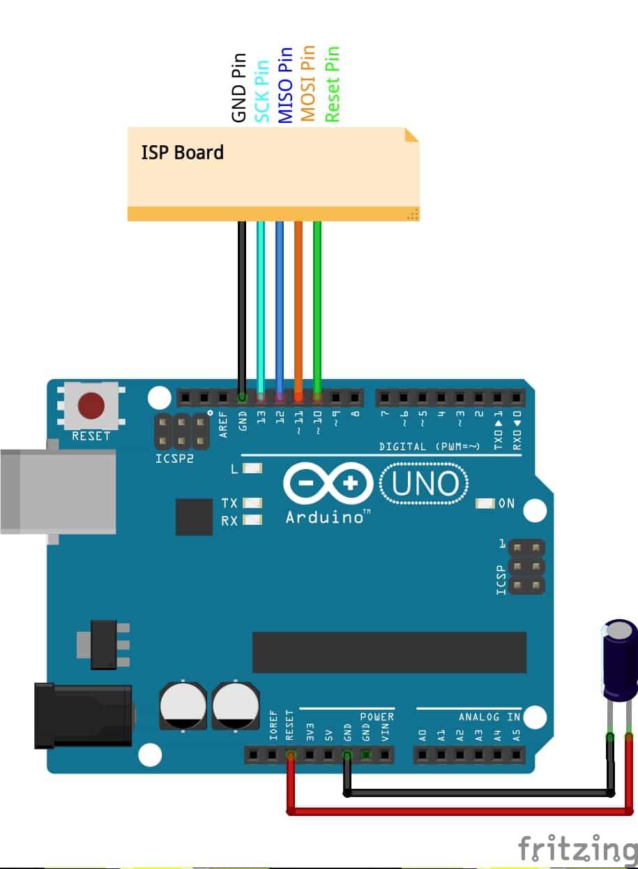
D10(Arduino) –> Reset (Target)
D11(Arduino) –> MOSI (Target)
D12(Arduino) –> MISO (Target)
D13(Arduino) –> SCK (Target)
GND(Arduino) –> GND (Target)
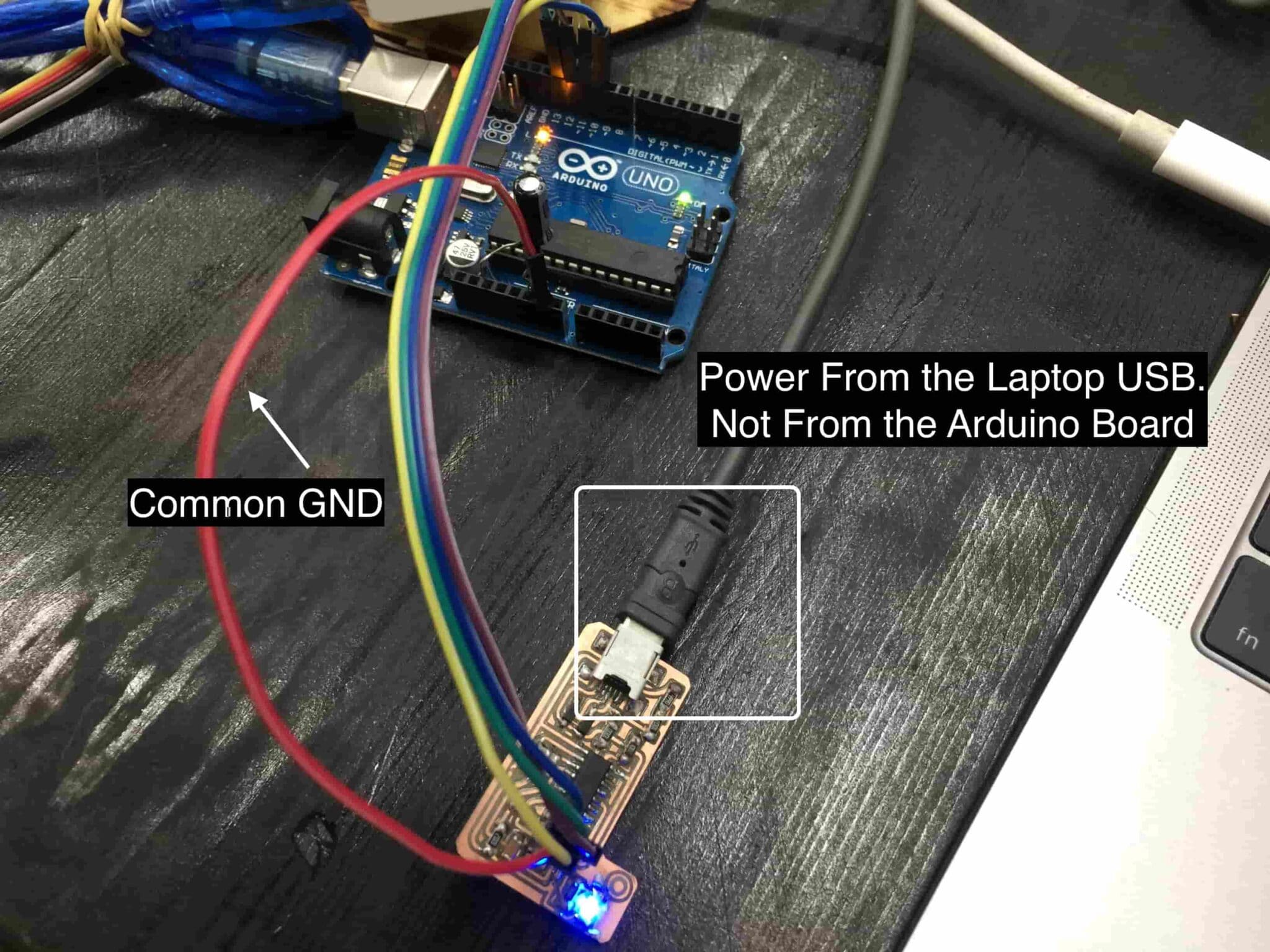
As you can notice we are connecting a 10uf capacitor between the Reset and the GND pin of the Arduino UBO board. As you notice, we are not providing power to our target board directly from the Arduino board. We are providing power to the FabISP AVR programmer board(target) by connecting it separately to the laptop through the USB port. And don’t forget to make a common GND between the two boards by connecting the GND of the FabISP AVR programmer board(target) board to the GND of the Arduino UNO(programmer).
After connecting the Arduino UNO board(Programmer) To the FabISP board(Target) we need to compile the FabISP firmware and upload it to the FabISP board. The Arduino UNO board will act as a bridge between my Laptop and the FabISP board. Since I’m using a Mac machine, I will download AVR CrossPack. CrossPack is a development environment for Atmel’s AVR® microcontrollers running on Apple’s Mac OS X, similar to AVR Studio on Windows. It consists of the GNU compiler suite, a C library for the AVR, the AVRDUDE uploader, and several other useful tools.” After heading to the AVR CrossPack website, click the “Download” button and install the .dmg file. That’s it!


Then we need to download the FabISP firmware from the link below. The Makefile which is inside the original firmware folder is ready to use with the avrisp2 or the usbtiny, if you will use a different programmer from these two options it will not work. So, I made some tweaks to that Makefile to make it compatible with the Arduino Uno that I use as a programmer. And it’s now ready to use with your Arduino UNO as a programmer you can download it from the link down below.
Now, we will open the terminal and navigate to the firmware folder. Then, clean any previously compiled files by writing make clean. Then we need to generate a new .hex that meets our new MakeFile. We will use the make hex command.


Then we need to write the make fuse command to set the fuses so the board will use the external clock. You should see a response like the one in the first image. Lastly, use the command make program to burn our firmware to the board to work as an AVR Programmer.


FabISP AVR Programmer Testing
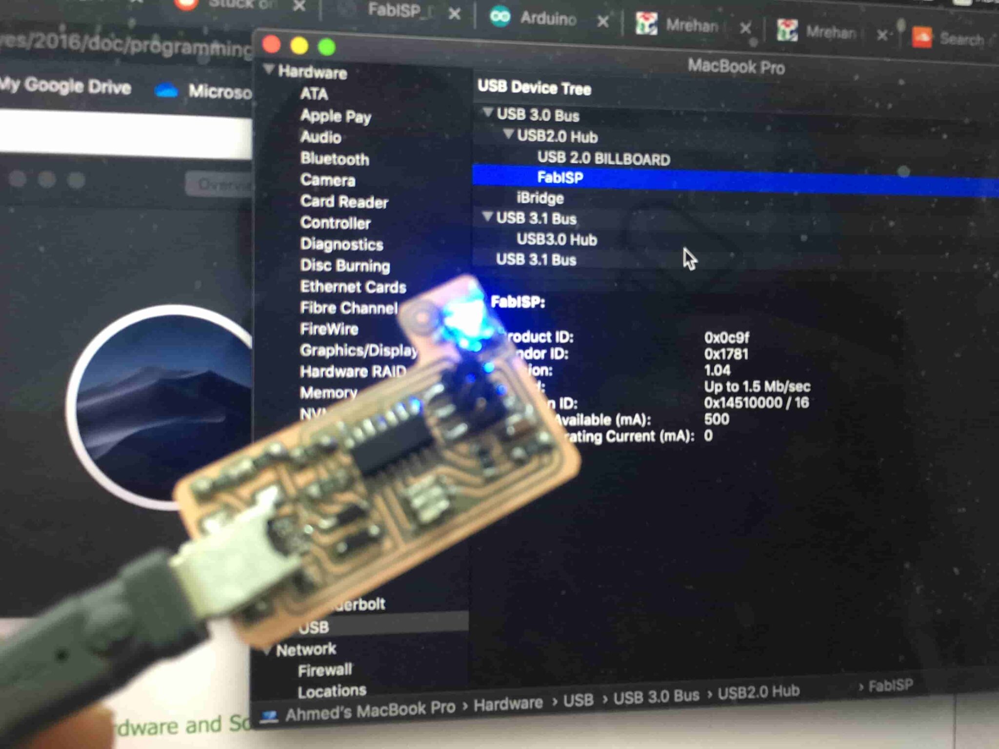
After finishing the previous steps, your computer should now recognize the board as an ISP. Since i’m using a MAC machine, click on the Apple logo, then click in “About This MAC”, then “System Report”.


Then from the left side menu under the “Hardware” section click on “USB”. your programmer should be recognized by your computer with the name FabISB. Which means your AVR ISP is now ready to work!

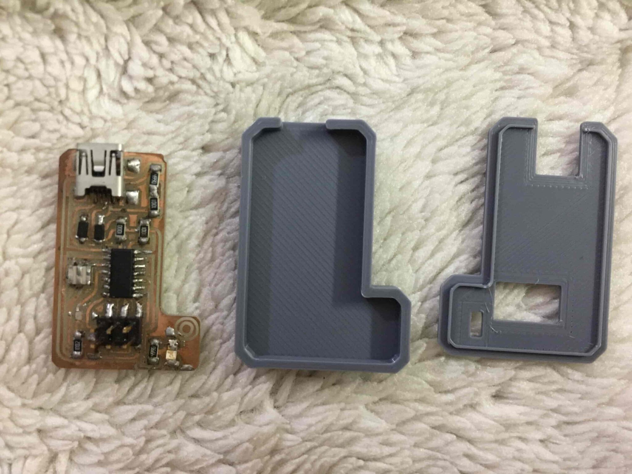
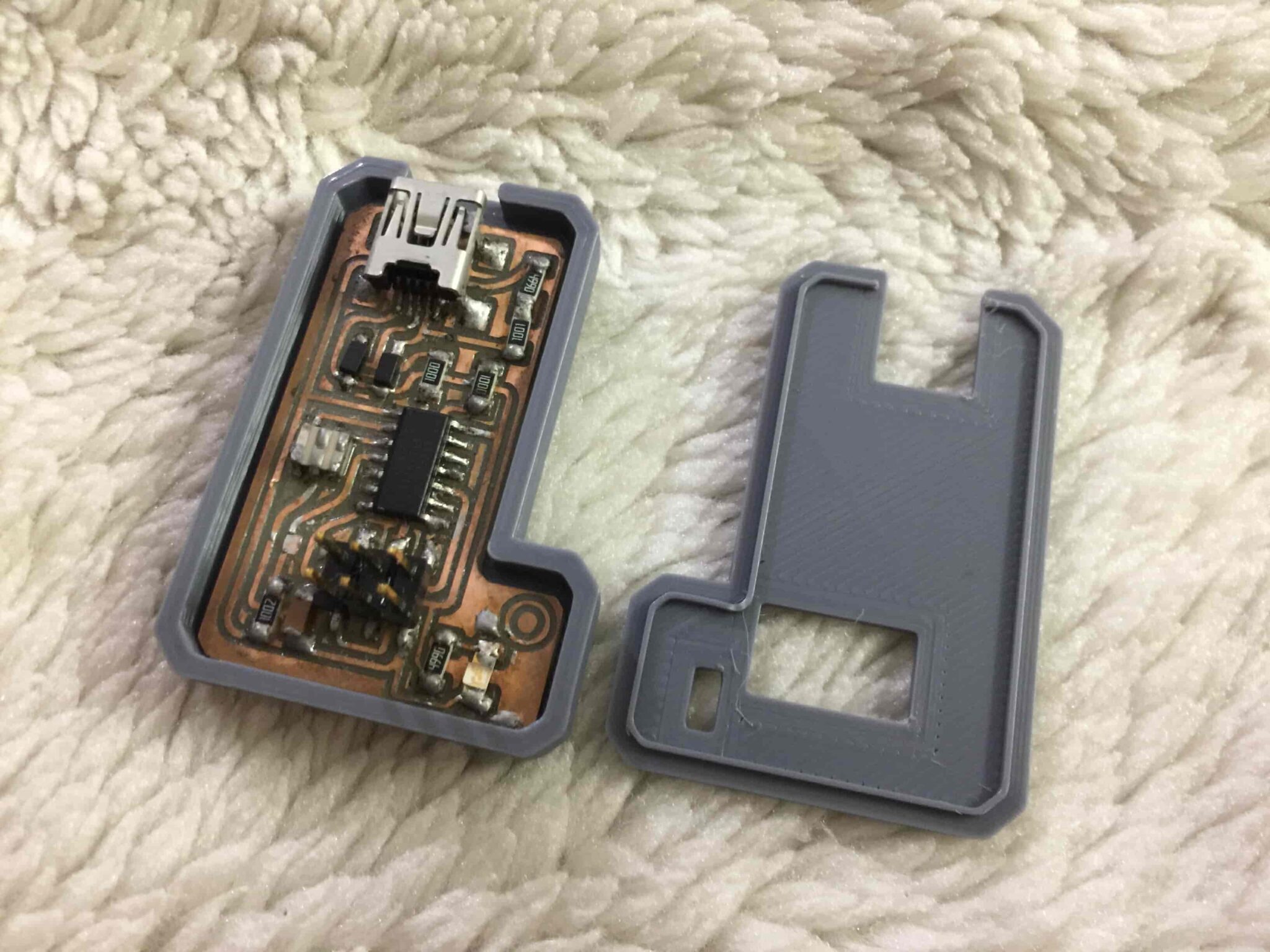
FabISP AVR Programmer 3d Printed Enclosure
I designed an enclosure for the Tiny AVR programmer you can download it from the links down below. I 3d printed these parts with 20% infill without supports.
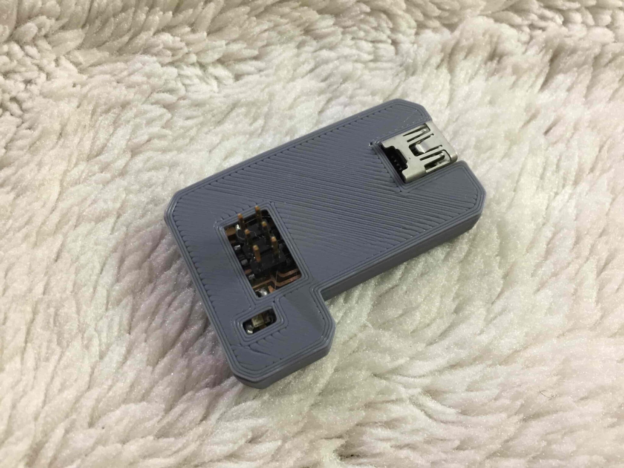
Here comes the end of the tutorial, thanks for your patience and check our upcoming tutorials on how to use this Tiny AVR programmer and how to program your own circuit boards. Don’t hesitate to drop down any question you want!


