
Introduction And The Big Picture
Tiny-Ciaroduino is a small-sized Development board based on the beautiful ATtiny85 chip from Atmel. Don’t get fooled by its small size, it’s powerful with great potential and well-documented resources built around it. We wanted to make a small-sized and low-cost development board that fits in any project without hesitation. You don’t need to give up your expensive Arduino or Raspberry pi board anymore to build your project. Blow up your cheap Tiny-Cairoduino board and buy another one, EASY!

There are a lot of open-source Duinos out there, I’m building one more open-source Duino-inspired board but with some addons and features that I was searching for. Tiny-Cairoduino is mainly inspired by the Digispark and the Trinket boards. Thanks to the open-source community. The main goal of the Tiny-Cairoduino board is to integrate the strength points from all the available ATTiny85 based dev boards and come out with a new beast that is easy to program and easy to play with on the hardware level too. And, totally open-source!
Our plan is to develop a whole set of shields that helps hobbyists and newbies to easily implement their hardware projects like if they are assembling lego bricks. We are currently working on that and we will be publishing these shields very soon.

I told you before, Don’t get fooled with its size! Despite being so small The Attiny85 chip has 8K bytes of flash memory and 5 I/O pins. All the 5 GPIO pins can be programmed as digital inputs or digital outputs. Including ADC(analog input) on four pins, PWM(analog outputs) on three pins -more can be achieved with software PWM-. It literally plug and play thanks to the preloaded bootloader that helps you to reprogram the board over USB like any Arduino board. Tiny-Cairoduino is also compatible with Arduino IDE. Even though you can program your Tiny-Cairoduino using the Arduino IDE, it’s not fully 100% Arduino-compatible. There are some things you trade-off for such a small and low-cost microcontroller!
- Tiny-Cairoduino does not have a Serial port connection for debugging so the serial port monitor will not be able to send/receive data. But, you still can reprogram your board through the USB connection.
Tiny-Cairoduino specifications:
- Support for the Arduino IDE 1.0 and later (OS X, Windows, and Linux).
- Built-in USB for programming.
- 5 I/O pins (2 are used for USB only if your program actively communicates over USB, otherwise you can use all 5 even if you are programming via USB).
- 8 KB flash memory (about 6 KB after bootloader),
- I2C and SPI (vis USI).
- PWM on 3 pins (more possible with Software PWM).
- ADC on 4 pins.
- On-board power indicator LED.
- On-board WS2818B addressable RGB led (connected on pin 4).
- Keyboard or other HID devices emulation (mouse, gamepad …).
- Handy pinout header to easily connect your Tiny-Cairoduino with the outside world.
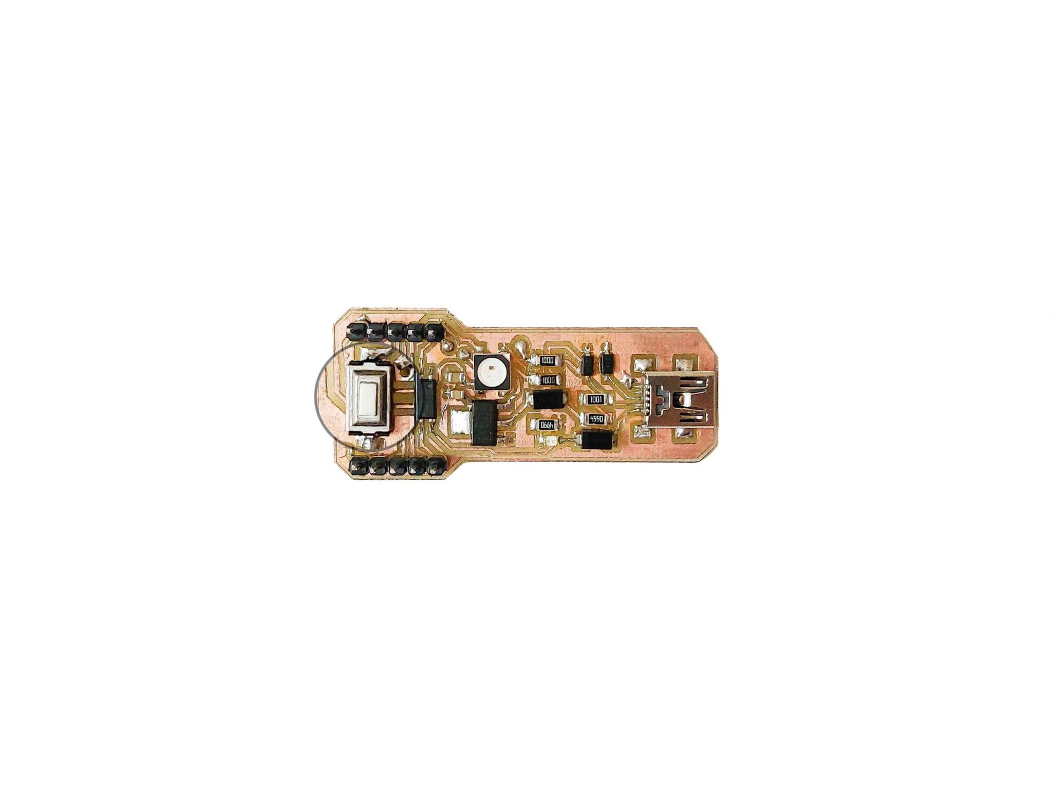
- On-board RESET button.
- A whole set of shields to maximize and expand the board functionality.
- Four mounting holes!
Guided Tour

Let me take you a tour through your Tiny-Cairoduino development board, Each board is assembled here at Make Some Stuff with love.
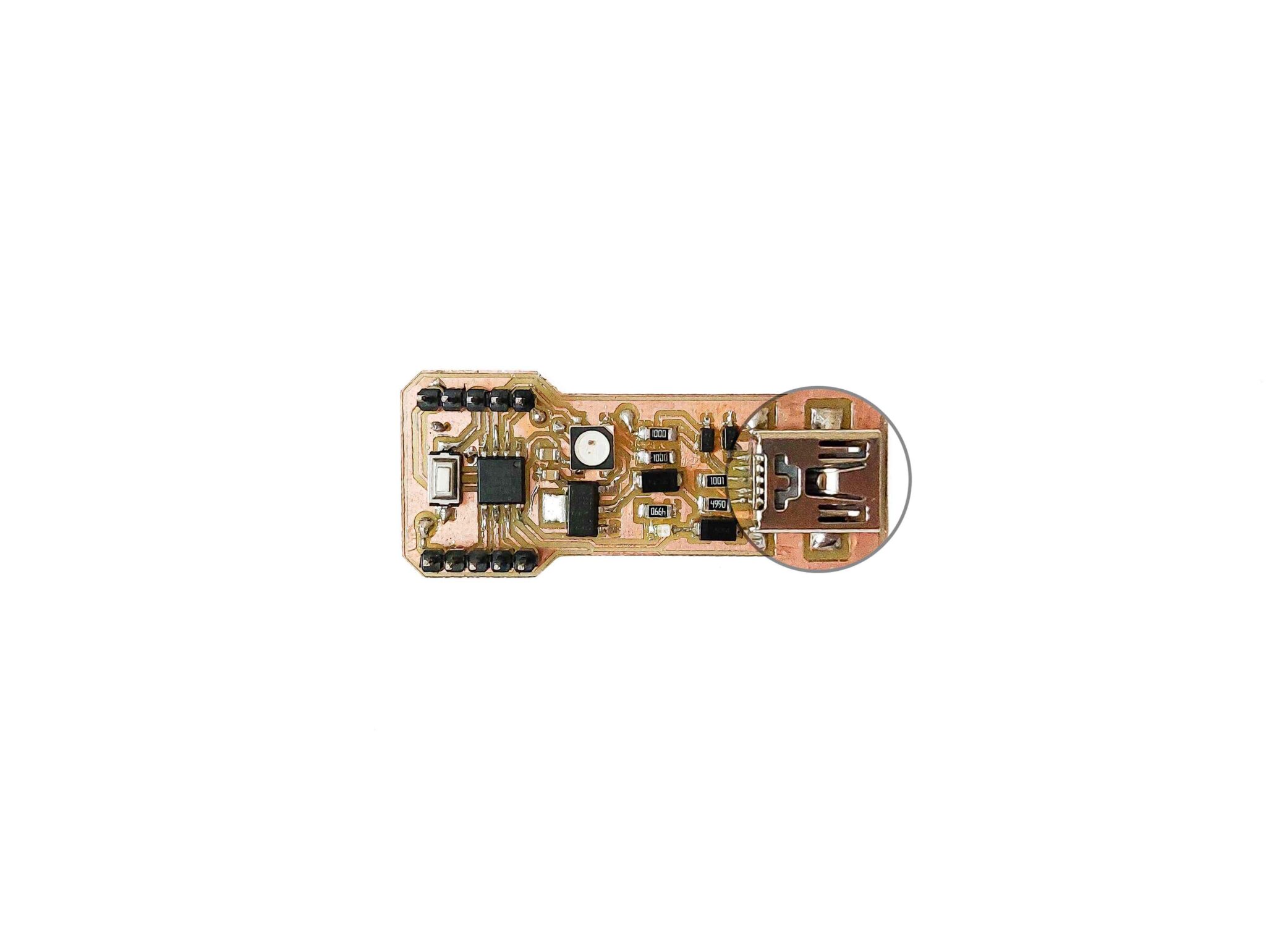
- Mini-B USB: We settled on the Mini-B USB for powering the board and code uploading for many reasons. The Mini-B USB is very rigid and solid on the PCB unlike other connector types like the Micro-B connectors which can rip off the PCB easily. Also, the Mini-B USB is a proper connector type, you can grab any USB cable with any length from any hardware store. Some Attiny85 Dev. boards use a PCB that slides into a USB port to cut costs, but that makes it hard to re-program and annoying to power with an external battery pack.
- Power LED: A cool power indicator LED. It lets you know when your board is powered up by being so lit!

- Reset Push-button: An onboard reset push-button launches the bootloader program when pressed. Making it easy to reprogram the board without unplugging and replugging the board to the computer.
- External reset pin: We bring out the reset pin so you can reset your board without reaching the onboard reset button. It’s handy when your board is inside an enclosure or a box and it’s hard to reach out, you can wire up a button to this pin to reset your board on the road.

- Breadboard-friendly header: You can easily plug the board on a breadboard and have a bigger space to wire things up.
- WS2818B RGB LED: An onboard WS2818B addressable RGB LED connected on pin #4. You can easily control it to make some cool stuff according to your needs.

- AMS1117-5V regulator: An onboard 5V 1A voltage regulator. It allows you to supply voltage from 7V to 12V on the Vin pin without fearing the needed 5V for the microcontroller. It does the work for you. Making the Tiny-Cairoduino proper for DIY projects and very easy to connect to a wall adapter, power bank, battery, or any other kind of power source.

Tiny-Cairoduino Pinout

Power Pins
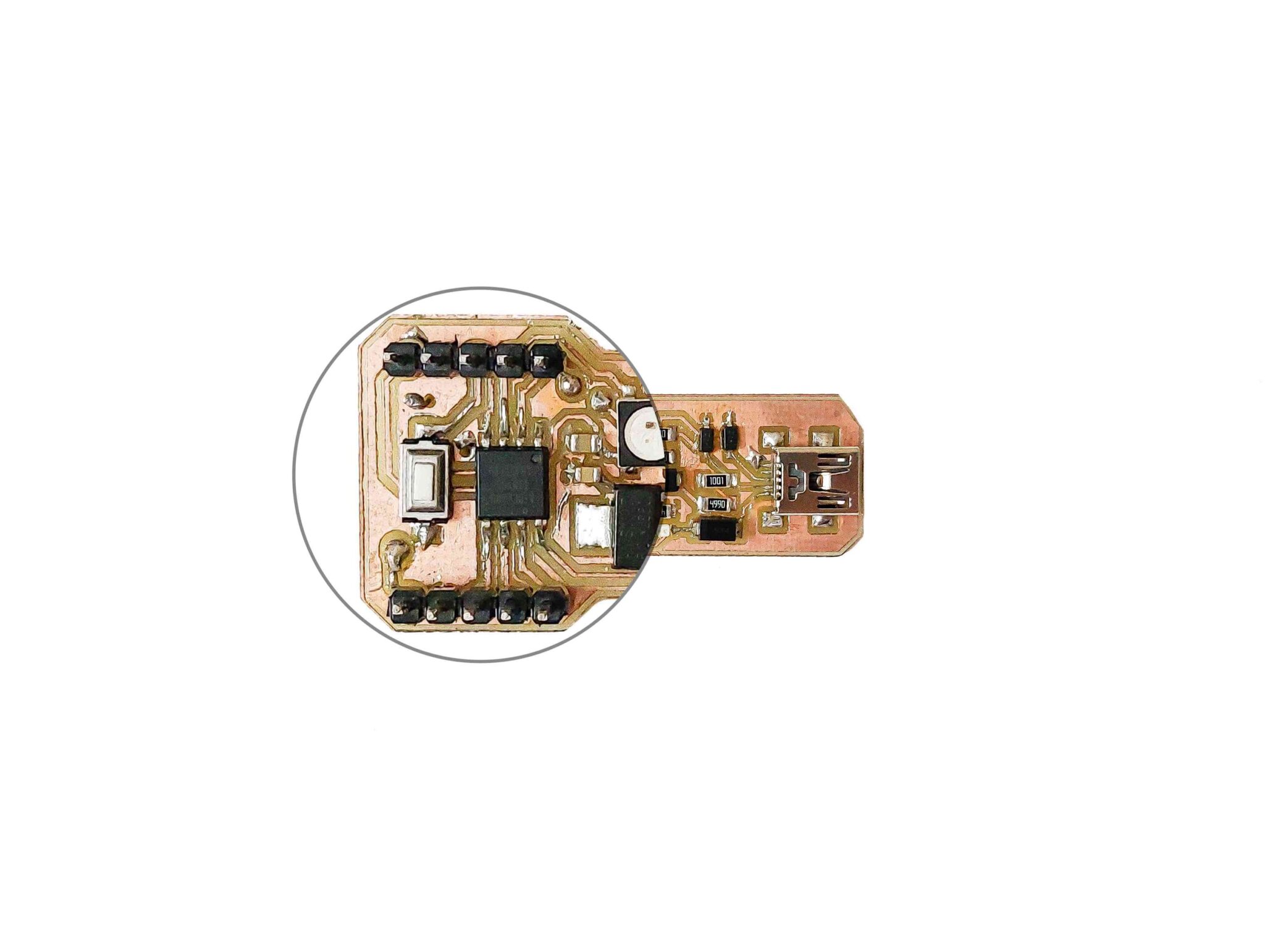
Let’s start with the power pins. On the top of the board, you will see three different power pins 5V pin, VIN pin, and GND pin.
- 5V pin: It’s a power positive pin connected to the output terminal of the voltage regulator and also connected to the USB 5V terminal. If you are powering your Tiny-Cairoduino board from your computer through the USB cable, you can use this pin to get 5V upto 500mA coming from your computer USB port, with it you can charge a battery, or control some output devices. If you are powering your Tiny-Cairoduino board from an external power source like a battery, power bank, or any other kind of power source through the VIN pin, you can use this pin to get 5V upto 1A coming from the onboard voltage regulator.
- VIN pin: You can use this pin to power up your Tiny-Cairoduino board from a battery, power bank, power adapter, or any other type of power source. Connect the positive terminal(+) of your power source to this pin and the ground terminal(-) to the Tiny-Cairoduino GND pin. Your power source needs to be between 7V and upto 12V.
- GND Pin: It’s the common ground pin of the Tiny-Cairoduino used for logic and power. It is connected to the USB ground and the AMS1117 voltage regulator. This is the pin you’ll want to use for any and all ground connections.
GPIO Pins
All the GPIO pins can be used as digital input or digital output pins, you can use them to read data from a sensor, control an LED, reading switch state, … They are all 5V logic pins. Each pin can provide upto 20mA of current. Don’t connect any component that draws more than 20mA directly to the GPIO pins like motors for example. You can use a transistor, relay, or motor driver instead.
The first three GPIO pins(#0, #1, #2) are all completely free you can program them without worrying about USB communication interference.
- GPIO #0: It’s connected to the ATtiny85 PB0 pin, it can be used as an output PWM pin, also can be used as MOSI pin(SPI communication), also can be used as I2C data pin(SDA I2C Pin).
- GPIO #1: It’s connected to the ATtiny85 PB1 pin, it can be used as an output PWM pin, also can be used as MISO pin(SPI communication).
- GPIO #3: It’s connected to the ATtiny85 PB1 pin, also can be used as SCK(SPI communication clock pin), also can be used as I2C clock pin(SCL I2C pin), also can be used as an analog input pin which is known as A1.
The remaining two GPIO pins(#3, #4) are connected to the USB port for USB programming. When the board is in the bootloader mode or in the middle of a program uploading these two pins are used to send/receive data to/from the computer. So, it’s highly recommended to not use them while you are reprogramming your board. Also, it’s recommended to disconnect any connections from these pins while uploading your program.
- GPIO #3: It’s connected directly to the ATtiny85 PB3 pin, It’s also used for USB programming, it also can be used as an analog input pin which is known as A3. it also can be used as a PWM output pin.
- GPIO #4: It’s connected directly to the ATtiny85 PB4 pin, It’s also used for USB programming, it also can be used as an analog input pin which is known as A2. it also can be used as a PWM output pin. It’s also connected to the onboard WS2818B LED.
- RST: The reset pin is connected directly to the ATtiny85 reset pin and to the reset push button. It can be used to restart your board in case you want to reset it. Or to enter the bootloader mode to easily reprogram your board without unplugging and replugging the USB cable. You can wire a simple push-button from the reset pin to the ground and press it if you want to enter the bootloader mode in case the board is inside an enclosure or a box and it’s hard to reach.
Installing The Board Drivers
To be able to program your board and make it recognizable by your laptop, you need to install some drivers. MAC and Linux operating systems already have the drivers installed. So, MAC and Linux users don’t need this step. Only Windows users need to install the board drivers.
We need to download the Digispark bootloader Windows drivers from the link down below. After extracting the .zip file, if you are using a 64-bit Windows OS you will need to use this installer “DPinst64”. And, if you are using a 32-bit Windows OS you will need to use this installer “DPinst”.

After finishing the installation process. Plug in your Cairoduino board to your laptop and open the device manager on your windows. Now you should find your Tiny-Cairoduino board listed under the “libusb-win32 devices” as “Digispark Bootloader”.

If you did not find it. Click on the “View” tab from the top menu bar and select “Show hidden devices”. Now, you should see “Unknown device” under “Other devices”.

Press right-click on “Unknown device” and select “Update Driver Software…”

select “Browse my computer for driver software”. Then select the location for the drivers we installed in the previous step. You can use the “Browse” button to select the drivers location.

Once you finish that and see the message “Windows has successfully updated your driver software” now unplug your board and plug it in again. You should now find your Tiny-Cairoduino board listed under the “libusb-win32 devices” as “Digispark Bootloader”.
How To Program Your Board
After installing the DigiSpark drivers, we are now ready to program our Tiny-Cairoduino board. By default, Arduino IDE does not contain the Digispark boards so we need to add these boards manually by ourselves. To do that, from the Arduino IDE top menu bar press on File > Preferences and add the link below in the Additional Boards Manager URLs then click ‘OK.
http://digistump.com/package_digistump_index.json
After that, from the Arduino IDE top menu bar press on tools > Board > Boards Manager and search by “Digistump AVR” then select “Digistump AVR Boards by Digistump” and click on install.


After installing the board on your Arduino IDE, now you can select the “Digispark (Default 16.5MHz)” board from Tools > Board under the Digispark AVR Boards.

Now, you are ready to upload your first program to the Tiny-Cairoduino board. Copy the code down below, paste it into your Arduino IDE and press the upload button. Once you see the message “Plug in device now … (Will timeout after 60 seconds)” in the messages display place on the bottom of the Arduino IDE program, press on the reset button of the Tiny-Cairoduino board. The code will get uploaded on your Tiny-Cairoduino board and the Arduino IDE will display “Micronucleus done. Thank you!”.
// NeoPixel Ring simple sketch (c) 2013 Shae Erisson
// released under the GPLv3 license to match the rest of the AdaFruit NeoPixel library
#include <Adafruit_NeoPixel.h>

// Which pin on the Arduino is connected to the NeoPixels?
#define PIN            4

// How many NeoPixels are attached to the Arduino?
#define NUMPIXELS      1

// When we setup the NeoPixel library, we tell it how many pixels, and which pin to use to send signals.
// Note that for older NeoPixel strips you might need to change the third parameter--see the strandtest
// example for more information on possible values.
Adafruit_NeoPixel pixels = Adafruit_NeoPixel(NUMPIXELS, PIN, NEO_RGB + NEO_KHZ800);

int delayval = 5; // delay for half a second

void setup() {
  pixels.begin(); // This initializes the NeoPixel library.
}

void loop() {
  for (int i = 0 ; i <= 255 ; i++) {
    pixels.setPixelColor(0, pixels.Color(i, 0, 0)); // Moderately bright green color.
    pixels.show(); // This sends the updated pixel color to the hardware.
    delay(delayval); // Delay for a period of time (in milliseconds).
  }
  delay(80);
  for (int i = 255 ; i >= 0 ; i--) {
    pixels.setPixelColor(0, pixels.Color(i, 0, 0)); // Moderately bright green color.
    pixels.show(); // This sends the updated pixel color to the hardware.
    delay(delayval); // Delay for a period of time (in milliseconds).
  }
  for (int i = 0 ; i <= 255 ; i++) {
    pixels.setPixelColor(0, pixels.Color(0, i, 0)); // Moderately bright green color.
    pixels.show(); // This sends the updated pixel color to the hardware.
    delay(delayval); // Delay for a period of time (in milliseconds).
  }
  delay(80);
  for (int i = 255 ; i >= 0 ; i--) {
    pixels.setPixelColor(0, pixels.Color(0, i, 0)); // Moderately bright green color.
    pixels.show(); // This sends the updated pixel color to the hardware.
    delay(delayval); // Delay for a period of time (in milliseconds).
  }
  for (int i = 0 ; i <= 255 ; i++) {
    pixels.setPixelColor(0, pixels.Color(0, 0, i)); // Moderately bright green color.
    pixels.show(); // This sends the updated pixel color to the hardware.
    delay(delayval); // Delay for a period of time (in milliseconds).
  }
  delay(80);
  for (int i = 255 ; i >= 0 ; i--) {
    pixels.setPixelColor(0, pixels.Color(0, 0, i)); // Moderately bright green color.
    pixels.show(); // This sends the updated pixel color to the hardware.
    delay(delayval); // Delay for a period of time (in milliseconds).
  }
  delay(100);
}


After successfully uploading the code on your Tiny-Cairoduino board, The on-board WS2818B LED should now start breathing between red, green, and blue colors. Congrats! You uploaded your first Arduino code to your Tiny-Cairoduino board.
Board Design
Before designing the schematic file, We must settle on the parts and the specific footprints that we will use to build this board. Since we want to make this board as small as possible. We decided to use only SMD parts. All the resistors and capacitors are in 1206 SMD footprint except only one capacitor in 0805 SMD footprint. To regulate the input voltage, we used an AMS1117-5V voltage regulator since it comes in a relatively small form factor but with great power. We used two Schottky diodes, one on the USB port and the other one on the voltage regulator output pin to protect them from any possible reverse current.
To identify our Tiny-Cairoduino board as a USB device to the host, we need to implement the USB communication circuit. Since, the signaling on the D+ and D− lines should be within 0V to 3.3V rails, while the host-supplied voltage is 5V. So we used two 3.3V Zener diodes on the D+ and D- lines to pull those lines two 3.3V. Ali Shtarbanov explained that part in an amazing way is this blog.
We put a 5050 SMD 5V addressable LED(WS2818B) on the board. It’s connected directly to pin #4 on the ATtniy85 chip. We used two 22uf SMD 0805 capacitors on the input and output pins of the voltage regulator to eliminate any ripples(noise) from those lines. We used one green 0805 SMD LED connected directly to the 5V line which acts as a power indicator. We used a generic two-pin SMD push button that connected to the ATtiny85 reset pin.


We love the open-source community! You can download the PCB Eagle source design files from this link
Board Fabrication
Before sending the Gerber files to PCBWay to manufacture the Tiny-Cairoduino board, I machined a test board on my Milling machine to test all the functionalities and to make sure that everything is working fine. After that, I sent the Gerber files to PCBWay who sponsors this build!


To make the PCB traces I used a 0.1mm v-bit. And, a 1.5mm 2 flutes square endmill to cut the PCB outline.


PCBWay is a PCB manufacturer and PCB assembler based in Shenzhen. They offer a broad spectrum of PCB prototyping, assembly, design, and CNC/3D printing services across five factories that are staffed by more than 520 employees. The coolest feature I use a lot before ordering my PCBs is the instant quote tool. PCBWay’s website is well designed and convenient. You can use the online instant quote tool to get an estimated cost for your board according to the fabrication parameters you select. Which made PCB ordering very easy and fast.
Uploading the bootloader
To be able to program your Tiny-Cairoduino board directly using the USB port, there’s a special program called “Bootloader” that runs on the microcontroller once you supply power to the board. The bootloader program is responsible for making the Tiny-Cairoduino board a USB recognizable device. and taking new programs from you and flashing them on the ATtiny85 chip memory. By default, the ATtiny85 does not come with the bootloader preloaded with any bootloaders. So we need to upload the bootloader to the ATtiny85 microcontroller manually. This is a one-time process.
We will use the same bootloader runs on the Digispark board “micronucleus tiny85” boot-loader, originally written by Bluebie. You can use any AVR programmer to upload the bootloader to the Tiny-Cairoduino board or use an Arduino UNO board which we will use in this step.
In the first step, we need to configure our Arduino UNO board as an ISP(In-System Programming) to work as an AVR programmer to the Tiny-Cairoduino board. Connect your Arduino UNO to your computer and open Arduino IDE then navigate to File > Example > ArduinoISP and upload the Arduino ISP code.


In the second step, we need to connect the Arduino UNO board to the Tiny-Cairoduino board as the wiring diagram down below. We are using a 10uf polarized capacitor on the reset and GND pin of the Arduino board.

In the third step, Connect your Arduino UNO board to your computer and open Arduino IDE. Find which port is your Arduino board connected to. In my case, my Arduino UNO board is connected to COM6 .We will need that information in the next steps

After this, download the bootloader burning files from the link down below. open the “Burn_AT85_bootloader.bat” and change the COM port number “PCOM5” with whatever COM port number your Uno is connected to. Save the changes before exiting.

Now move the edited “Burn_AT85_bootloader.bat” and “ATtiny85.hex” files into the Arduino IDE root folder (C:\Program Files (x86)\Arduino). After that right-click on the “Burn_AT85_bootloader.bat” and select “Run as administrator” it will take about 5 or 6 seconds to burn the bootloader to the Tiny-Cairoduino board. If all went well, you should receive this message “AVRdude done. Thank you. Press any key to continue…”.

Now, your ATtiny85 chip is flashed successfully with the bootloader. You can now connect the Tiny-Cairoduino board directly to your laptop and use it like any development board.


